


Love
of
detail.
Technical knowledge
For the facade
The initial idea is followed by the sketch, and the sketch is then turned into a drawing. For the large variety of ceramic facades, there are also many different ways of installing them. Learn more about these topics in the following section: Which brickwork bonds are possible? What is meant by facing formwork, formwork spacing or the air layer? And discover many drawings on relevant technical details.
Klinkerpedia
basic knowledge of ceramic facades
Informing
Discover condensed knowledge about all aspects of ceramic facades and frequently used specialist terms.
Here is a brief overview of a few of the key terms associated with ceramic facades. You can contact us at any time about specific topics relating to your project. Our Field Service and in-house Service team will be pleased to give you detailed advice on precisely how to implement your project.
TECHNICAL TERMS FOR CERAMIC BRICKWORK
In contrast to monolithic construction, the formwork shell separates the various components involved in the building of a wall. In this way, every function is optimised consistently in the same way.
This provides the following benefits:
• the foundation and load-bearing wall absorb the structural loads
• the thermal insulation is on the optimum side in terms of physical building structure
• humidity penetrating from the residential area is dissipated by the air space
• protection against heavy rain is assured for insulation material and structure
• lower energy loss and reliable thermal insulation are optimised
• effective acoustic insulation is provided
• an extremely long service life (up to 100 years and more) is assured
• operating costs are minimised due to the almost zero-maintenance construction.
The air layer between insulation and ceramic brickwork prevents the ingress of damp into the layer of insulation. For optimum thermal insulation and long-lasting preservation of the facade, we recommend an air layer of 40 mm.
The formwork spacing comprises the thickness of the thermal insulation and the air layer. Formwork spacings up to 400 mm and more are current state-of-the-art technology and can be used without any problem with wire or dowel anchors, covered by building authority approval. Stainless steel consoles to dissipate facade loads exist for virtually all formwork spacing.
Before final production, all facade details always need to be clarified, and shaped slabs may need to be ordered. When using prefabricated ceramic components, the relevant drawings must be signed off by the planner to enable the shaped slabs with a swallowtail to be produced together with the ceramic elements for the brickwork that is to be built on site. The joint color also needs to be defined. For this, we recommend a mortar in mortar group IIa (pointing mortar).
GIMA ceramic elements are walled up with pointing mortar (mortar group IIa) for low-absorbency and non-absorbent slabs, with rendered joints. In accordance with ATV DIN 18330, Para. 3.2.5, the rendering of joints is a mandatory task, meaning that brickwork and pointing work constitute a single operation (retrospective pointing of joints is not advisable). There is a huge variety of colors of pointing mortar to suit different buildings, and it is advisable to do some samples on each building before starting work.
There are many ways to process a joint, including plastic hoses, strips of timber or jointers. These tools can significantly influence the character of the facade: rough or smooth, rounded inwards or slightly insert – to suit the taste of the planner. All pointing work should employ the same consistency of mortar to prevent differences in joint color.
A freshly smoothed joint (consistency of mortar still very soft) turns light whereas a joint smoothed late (when the mortar is already firmly set) turns dark. Ensure that the joint is always produced without any air cavities. If the position of the slabs needs to be corrected, remove all of the mortar, then apply a fresh batch. Do not reuse mortar that has been removed. Remove mortar residue from the surface of the stone while still fresh. To protect the brickwork from damp penetration, ensure that the mortar expanding backwards into the air layer is scraped off, and that any mortar that drops off is removed on a daily basis through the apertures provided at the base point.
DISTRIBUTION OF EXPANSION JOINTS
Facing formwork must be fitted down its full length to the total area of its supporting surface. When different materials are used for the supporting surface (e.g. concrete on stainless steel consoles), vertical expansion joints must be installed.
To be supported across a total surface area, the facing formwork must protrude by no more than 25 mm with a wall thickness of 115 mm and by no more than 15 mm with a wall thickness of 90 mm. Construction tolerances and the supporting surfaces (e.g. a bevel on the front of the stainless steel consoles) must be taken into account.
With a wall thickness of 115 mm, if even less of the supporting surface area is employed – up to 38 mm is possible – load must be removed from both storeys. Failing this, facing formwork up to a height of twelve metres can be used without load support, providing that the facade geometry permits this.
With a wall thickness of 90 mm, horizontal support should be provided at regular spacings of about six metres. For buildings with two full storeys and a pitched roof triangle of up to four metres, no additional load supports are required. A structural verification can permit a deviation from this rule. Facing formwork with a thickness of 90 mm can be extended to heights above ground level of up to 20 metres.
The sequences of movement always need to be coordinated. Console rigidly direct the forces of the load-bearing structure into the facing formwork. The supporting structure, especially if made of concrete, is subject to different distortion characteristics to the facing formwork. If exposed to direct sunlight, facing formwork can heat up to as high as 80°C but the supporting structure remains cool. This results in stresses that manifest themselves as cracks in the facing formwork. As time passes, these cracks can damage the pointing as a result of the combined actions of water and sub-zero temperatures.
As a rule, expansion joints have a minimum width of 15 mm. With horizontal load supports, observe the material widths of the console. The visible horizontal joint can then be much wider than 15 mm. Take due account of building expansion joints in the facing formwork. These are usually much wider than 15 mm.
In relation to the distribution of expansion joints, always pay attention to the format and color of the stone and the type of wall-mounted installation. Dark ceramic heats up more than light-colored ceramic. On big stone formats, joints occupy a smaller proportion of total surface area than small ceramic elements, but that also means that the joints on big formats have to be able to absorb more distortion. In the air layer, heat is dissipated by the chimney effect, but this not apply to core-insulated wall-mounted structures.
There are no definitive specifications for the distances between vertical expansion joints. The standards only provide recommendations. In practice, depending on stone format, color, design and cardinal direction, lengths of approximately eight to a maximum of twelve metres are assured.
Vertical expansion joints must always be arranged at the corners. The wall panels are routed around edges by no more than 240 mm. As a rule, the head width is the dimension of the expansion joint. Wall panels with roughly equal leg lengths to a maximum of five metres can also be installed without vertical expansion joints at the edges. The sub-division of expansion joints provides a big number of options. Horizontal expansion joints result from technical parameters while vertical expansion joints are determined largely by the geometry of the facade and the design concept of the planner. Here we always recommend a dialogue between planner and technical adviser.
The expansion joints must be sealed in the most durable manner possible. This is usually achieved with duroplastic compounds, or with expansion joints. The choice of colors is more limited with expansion joints. As a rule, it is possible to achieve an excellent color match between duroplastic joints and the existing mortar joints, and they can also be sanded down. Duroplastic joints need to be replaced roughly every 10-15 years, depending on design quality. When planning expansion joints, you should aim to have as few as possible.
Technical
drawings
Drawing
Of bonds, once you have chosen the color and format of your ceramic element, technical advice then has a big role to play.
Here you can find detailed drawings of base point configurations, window sills and load dissipation. We also explain which different brickwork bonds are possible. Here is an excerpt of the technical details. During the project consultancy and planning stages, you receive personal support from our employees as well as our technical brochure with numerous other solutions and drawings.
Numerous possibilities
Brickwork bonds


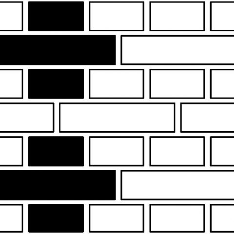


You will find further details in the planning folder ‘zweischalige Wand’, from the ‘Bauen mit Backstein’ (Building with Brick) German initiative. Here you can find further basic knowledge and practical examples associated with building with brick.